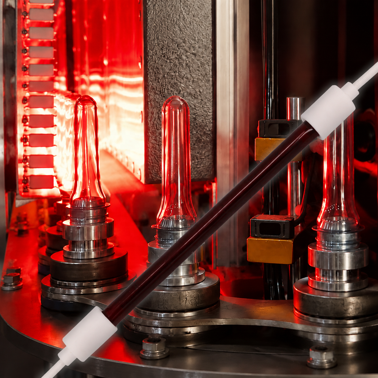
How Infrared Heating Works in PET Preform Reheating
In two-step stretch blow moulding (ISBM), preform reheating transforms rigid, injection-moulded preforms at ambient temperature into an elastic, thermoelastic state ready for biaxial stretching and high-pressure blowing. Infrared (IR) radiation serves as the standard energy transfer mechanism because it delivers high energy flux directly into the polymer matrix without requiring physical contact. Understanding how infrared radiation interacts with polyethylene terephthalate (PET) resin, oven reflectors, spindle rotation, and forced cooling air is essential for establishing stable blowing windows and preventing common moulding defects.
1. Process Position: The Reheat Stage in Two-Step SBM
Two-step stretch blow moulding decouples preform injection moulding from container blowing. Ambient-temperature preforms (typically stored in gaylords or octabins) enter the blow moulding machine through an unscrambler, pass down an infeed rail, and are loaded onto rotating mandrels (spindles) on a continuous conveyor chain.
[Infeed Preforms] ──> [IR Heating Oven (Rotating Mandrels)] ──> [Thermal Equilibration (Soak)] ──> [Blow Mould Cavity]
                            │                                                                               │
             [Radiant Heat + Shielded Neck Cooling]                                            [Stretch Rod + Dual-Stage Blow]
Within the heating oven, preforms travel through a tunnel lined with horizontal quartz infrared heating lamps on one side and optical reflectors on the opposing side. The objective is not simply to warm the material, but to bring the amorphous PET polymer into its optimum rubbery processing window—typically between95°C and 115°C(well above the glass transition temperature $T_g \approx 78^\circ\text{C}\text{–}81^\circ\text{C}$ and comfortably below the thermal crystallization onset at $\approx 135^\circ\text{C}\text{–}140^\circ\text{C}$).
2. Fundamental System Components
A commercial preform heating module consists of five coupled subsystems:
| Subsystem | Primary Function | Operational Impact |
|---|---|---|
| Quartz Infrared Emitters | Deliver radiant flux primarily in the short-wave ($1.0\text{–}1.4\ \mu\text{m}$) and near-infrared bands | Filament operating temperature ($\sim 2200\text{–}2500\text{ K}$) determines spectral peak and penetration depth |
| Back & Counter Reflectors | Redirect unabsorbed radiation back into the preform path | Specular aluminum or ceramic white coatings control forward radiation efficiency |
| Rotating Spindles (Mandrels) | Rotate preforms continuously ($360^\circ$) as they traverse the oven | Ensures circumferential thermal symmetry around the preform circumference |
| Ventilation & Surface Cooling Air | Sweep ambient air across outer preform surfaces | Prevents preform skin overheating and suppresses premature surface haze |
| Neck Protection Rails | Shield injection-moulded thread finishes from direct radiation | Maintains neck finish below $50^\circ\text{C}\text{–}55^\circ\text{C}$ to prevent thread distortion and ovality |
3. Radiation Penetration vs. Thermal Conduction
A frequent misconception in plant operations is assuming that infrared lamps heat the entire preform wall uniformly like a microwave. In reality, infrared heating in PET involves two competing mechanisms:
- **Radiant Absorption:**PET exhibits strong absorption bands in the infrared spectrum (notably around $1.4\ \mu\text{m}$, $1.66\ \mu\text{m}$, $2.2\text{–}2.4\ \mu\text{m}$, and fundamental vibration bands beyond $3.0\ \mu\text{m}$). Short-wave infrared radiation ($0.8\text{–}1.4\ \mu\text{m}$) penetrates relatively deeply into the material wall before being fully absorbed, whereas medium-wave radiation ($>2.0\ \mu\text{m}$) is absorbed almost entirely within the first few tenths of a millimeter of the outer skin.
- **Conductive Dissipation:**Because virgin PET is a poor thermal conductor ($k \approx 0.15\text{–}0.24\ \text{W}/(\text{m}\cdot\text{K})$), heat absorbed at the outer surface conducts slowly toward the inner core.
If preforms are heated purely by external surface absorption without sufficient penetration or soak time, the outer surface will overheat (reaching crystallization temperatures and turning cloudy white) while the inner wall remains below its natural stretch temperature, resulting in severe micro-cracking (pearlizing) during stretch blow moulding. To mitigate this gradient:
- High-efficiency short-wave quartz lamps (such as the Goldisgood GIG-010 clear series) are utilized to maximize volumetric penetration into the preform wall.
- Counter-current cooling airflow is blown over the outer surface to continuously strip excess surface heat.
- An oven exit soak zone (often lasting 2 to 4 seconds before mould entry) allows temperature equalization across the wall thickness.
4. Key Factors Governing Thermal Distribution
Achieving an optimal preform temperature profile requires balancing four process boundaries:
- Axial (Vertical) Heat Profiling: The preform does not expand uniformly. The shoulder, label body, and base require significantly different amounts of elongation. The oven organizes lamps into vertical zones (Zones 1 through 8 or more), each independently modulated to provide customized heat inputs along the preform axis.
- Circumferential Uniformity: Any slippage or failure in the mandrel rotation chain causes uneven exposure, leading directly to wall thickness eccentricities and bent bottles.
- Line Speed & Exposure Time: Increasing line speed reduces residence time inside the oven, requiring higher lamp output voltages or additional oven modules. However, running lamps at excessive power on short tracks risks steep thermal gradients.
- Ambient Temperature and Drafts: Factory seasonal temperature swings and uncontrolled drafts through machine doors can disrupt the cooling boundary layer and destabilize preform surface temperatures.
5. Process Qualification and Verification
Before making adjustments to preform heating profiles or changing emitter hardware, plant engineering teams should record the following baseline metrics:
- **Oven Electrical Configuration:**Document applied voltage percentages per zone, line supply voltage stability, and emitter part numbers.
- **Preform Surface Temperature Profile:**Use a calibrated infrared pyrometer (filtered at $3.43\ \mu\text{m}$ or $5.0\ \mu\text{m}$) at the oven exit to capture top-to-bottom surface readings.
- **Preform Core Temperature:**Cut cross-sections of preforms directly at the oven exit using an insulated probe or destructive thermal imaging to evaluate the inner-to-outer wall delta (target: $\Delta T < 4^\circ\text{C}\text{–}6^\circ\text{C}$).
- **Bottle Wall Distribution:**Measure cross-sectional wall thickness of blown containers at designated vertical stations (shoulder, mid-body, base transition) to verify that material distribution matches container specifications.
Related Guides
- PET Preform Heating Zones Explained
- How to Specify a Replacement PET Preform Heating Lamp
- Uneven PET Preform Heating: What to Check
Related Goldisgood Heating Solutions & Engineering Support
Plant engineering and maintenance teams evaluating preform reheating setups or sourcing replacement quartz emitters can access verified product specifications and technical support through Goldisgood:
- **Clear Short-Wave Quartz Emitters (GIG-010 Series):**Designed for high-penetration volumetric preform heating in linear and rotary blow moulding ovens. View Specifications on Goldisgood
- **Integral White Ceramic Reflector Lamps (GIG-011 Series):**Delivers a 180° directional radiant pattern to maximize forward flux and reduce sensitivity to degraded oven back-mirrors. View Specifications on Goldisgood
- **Application Engineering & Process Audits:**Sourcing assistance for specific heated lengths, non-standard voltages (230V, 400V, 480V), and specialized ceramic bases (SK15, R7s). Contact our engineering support directly at
info@goldisgood.comor visit Goldisgood.
Sources & References
- Society of Plastics Engineers (SPE), Polymer Engineering & Science: “Radiative and Convective Heat Transfer in PET Preform Reheat Stretch Blow Moulding.”
- American Society for Testing and Materials (ASTM) D746 / D3418: Standard Test Methods for Transition Temperatures of Polymers by Differential Scanning Calorimetry.
- US Department of Energy (DOE) - Industrial Efficiency & Decarbonization Office: Process Heating Assessment and Infrared Energy Systems Guide.
- Goldisgood Technical Specification: GIG-010 Clear Quartz Short-Wave Emitter Mechanical and Thermal Data.